Continuing our Adventure #
Picking up where we left off,
This lil’ synth works, but it doesn’t give us much control, and unlike a real instrument, after we let go of the key it just immediately stops. Similarly, most real instruments have a either a bit of a pluck at the start or a more gentle fade in.
This leads us to the idea of envelopes. In music, you’ll often want to draw a shape that evelopes a signal. That is, it contains it and determines when it is active and how much. We want to envelope our volume signal - that is, we want to shape it more than the basic on/off that we have right now.
One of the most common shapes to use for enveloping is called the ADSR. This stands for Attack Decay Sustain Release and is called such because, well, it has those four stages.
In an ADSR, the Attack Decay and Release knobs set the amount of time the stage takes. So, with a long attack, the sound will fade in. With a long release, the sound will take a while to get loud - assuming you’re using the envelope to control volume, that is.
The Sustain sets the level the envelope will rest at as long as the key is held, and the Decay is how long, after the attack, it takes to get to the sustain level.
So, to be very clear, the Sustain is the odd one out. The Attack, Decay, and Release stages are all the amount of time, the Sustain is a level.
So, let’s put this to use.
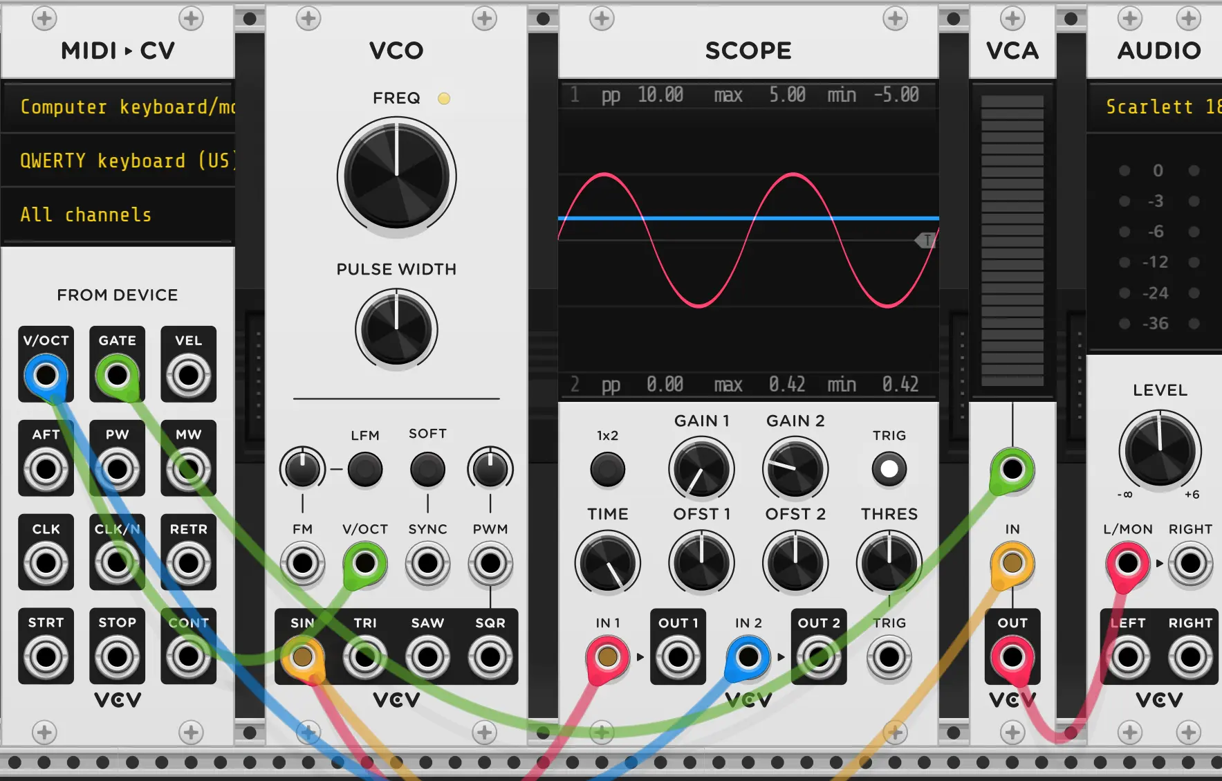
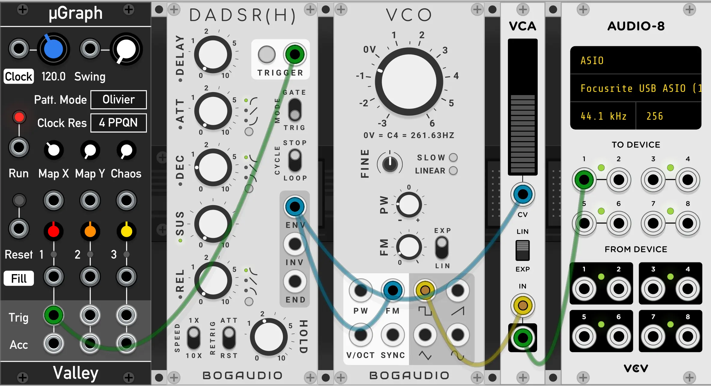
- Ensure you have a setup match that in the 1st screenshot on this page.
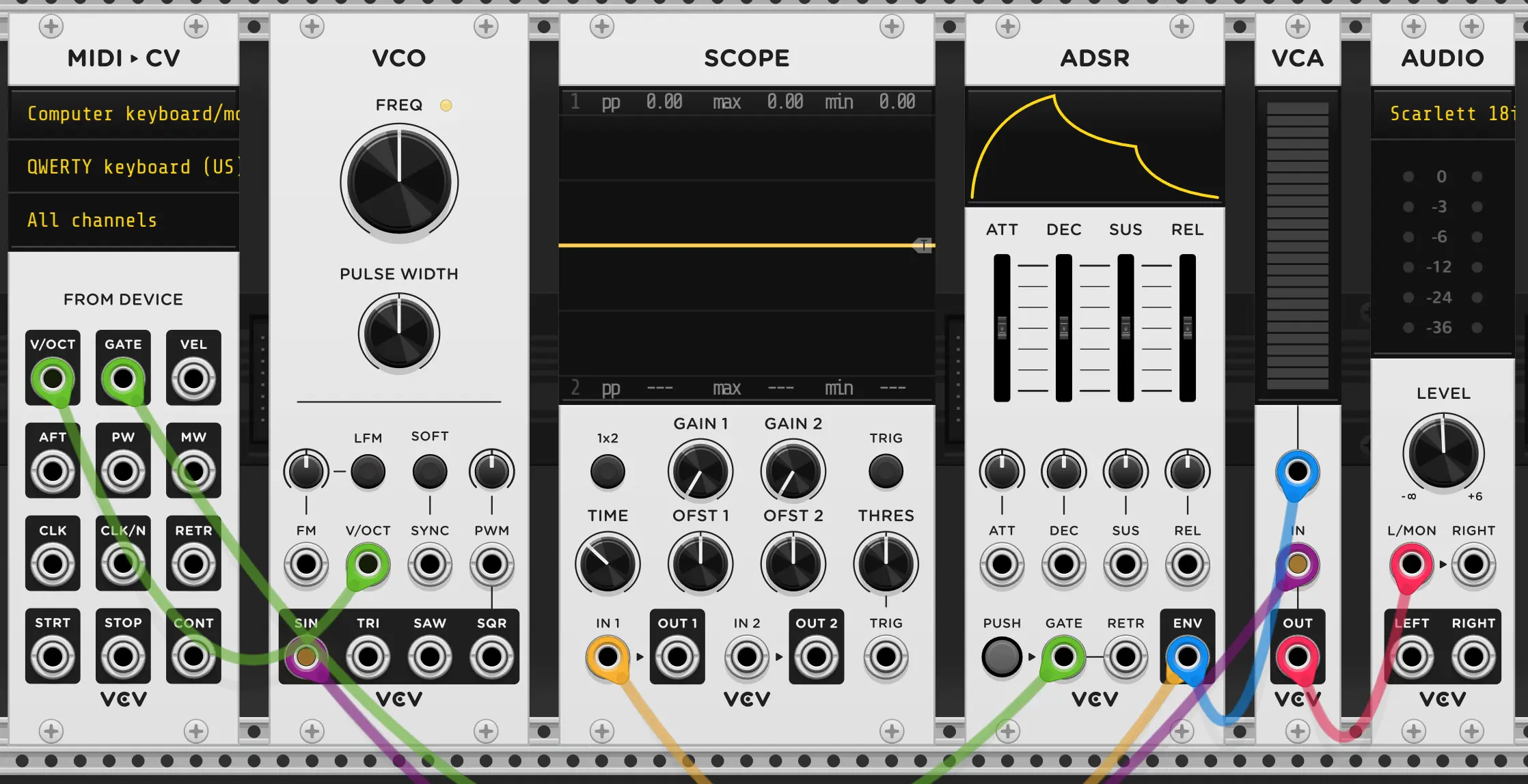
- Right click in the empty space and add the ADSR module. (it doesn’t match the GIF, due to an update). Place it before the VCA
- Remove both cables going into the SCOPE. Right click the SCOPE and select
initializeto reset it to default settings. - Place a new cable going from the
ENVoutput of the ADSR to theIN1of the SCOPE - Try pressing the
PUSHbutton on the ADSR. You should see a signal on the SCOPE. Try changing how long you hold thePUSHbutton for. You may want to adjust theTIMEknob on the SCOPE to the left to see the signal better. - Drag the wire that is connected to the top of the VCA (coming out of the MIDI ▶ CV’s
GATEoutput) to theGATEInput on the ADSR. - Add a new wire going from the top input of the VCA to the
ENVoutput of the ADSR (Stacking on top of the cable that’s going to the SCOPE). - Try hitting some keys on your keyboard, You should now hear the effect of the ADSR on the volume.
- Try changing the sliders on the ADSR and playing new notes.
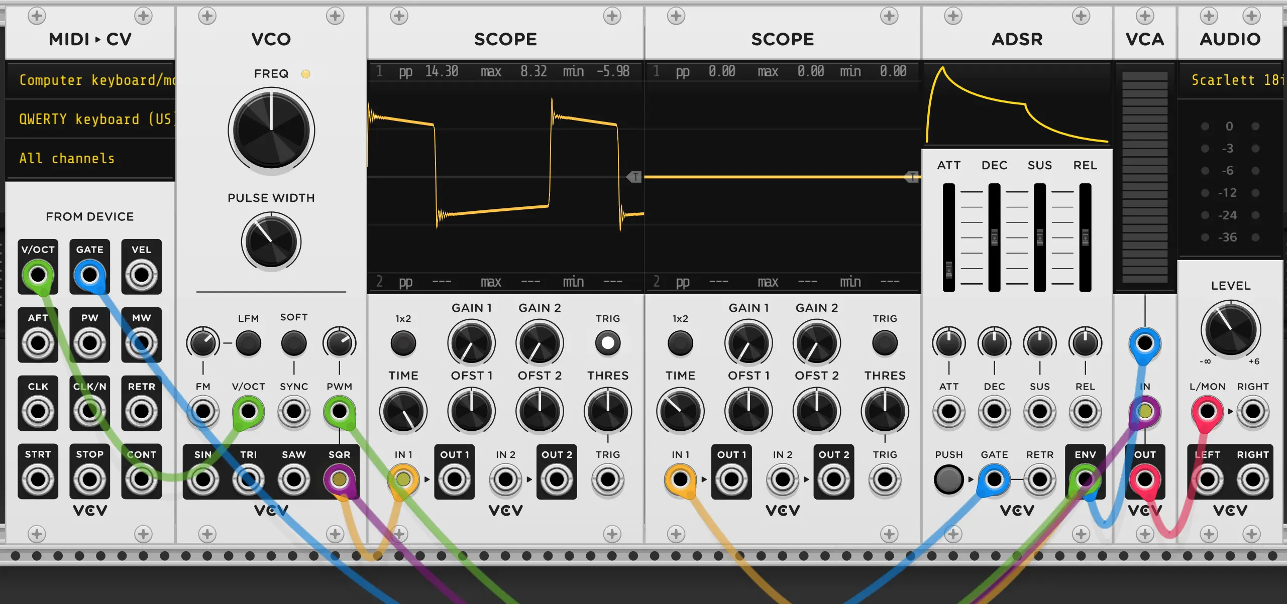
- Move the cable connected to the
SINoutput of the VCO to theSQR(Square) output of theVCO. - Add a second SCOPE module (hover over the existing one and press D )
- Setup the new SCOPE to view a fast moving wave by cranking the
TIMEknob and engaging theTRIGbutton. - Connect the
IN 1of this second scope to theSQRoutput of the VCO. - Try adjusting the
PULSE WIDTHknob on the VCO and observe the view in the scope and sound while playing notes. - Try connecting a wire from the
PWMinput on the VCO to theENVoutput on the ADSR, then adjust the small knob directly above thePWMinput on the VCO. This will change how much Pulse Width Modulation is being done by the envelope to the VCO. - Adjust this small knob above the
PWMinput and setting on the ADSR to get different sounds. Try changing the baseFREQof the VCO to be lower pitch. You may want to adjust theTIMEknob on the scope to be able to see the square wave well as you turn the frequency down.
Wow, that sure got tasty in a hurry, right? Well, how about we see just how flavorful it is. To do this, we finally need to bust out the spectrum analyzer. Unfortunately, VCV does not have one built in. This means you’ll need to.
- Go to https://vcvrack.com
- Make an account, sign in, etc.
- Go to https://library.vcvrack.com/Bogaudio/Bogaudio-AnalyzerXL and press + ADD in the top left. (don’t worry, it’s free.)
- Go into the VCV software, at the top, login with you’re new account
- Update plugins, etc. Restart VCV.
- Right click in the empty space, and the analyzer should now be available.
Okay, now that you have it installed,
-
Add the analyzer to your patch. Connect the top input the output of the VCA (stacking on the same wire that goes the
L/MONinput of the AUDIO module) -
Play some notes and adjust the
PWMandFREQknobs of the VCO while looking at the result both on the SCOPE and on the ANALYZER-XL module.If you can’t see everything on your screen at once, ctrl + + & ctrl + - OR ctrl + scroll-wheel can be used to zoom in and out. ↑ , ↓ , → ,← or holding the scroll wheel and dragging can be used to pan around
Okay, let’s see how this responds if we add some vibrato.
- Add an LFO and connect the
SINoutput tho theFMinput of the VCO and adjust the knob above the VCO just enough so you can hear the pitch wobble -FMis Frquency Modulation, by the way, and is (skipping a few details) effectively just being added to theV/OCTsignal internally to the VCO, that’s why it’ adds pitch-wobble. - Observe how at high rates it makes the spectrum analyzer a bit blurry, but at low rates we can see bumps wobble with the FM.

[TODO] The music chapters are actively being rewritten (Jan, 2023)
So far we’ve done everything with a basic VCO which can only output either a Sine, Triangle, Sawtooth, or Square wave - and you should experiment with those outputs and see how each sounds - but there’s a whole world of other sound sources out there for us to explore, so now that you’ve gotten your toes wet with VCV and hopefully understand the fundamentals, lets move on to Sound Sources .
- Replace the VCO with a WT-VCO
- Get Some modules from the library
Bog Analyzer- Hora Snare
- Hora Hat
- Hora Deep
- Clocked
- Comp II
- Plateau
- Befaco Slew
- Befaco Dual AT
- Voxglitch Digital Seq
- Palette (Plaits)
- Topograph (For ppqn)
- Add a filter, high level explain LP, HP, BP + resonance
- Envelope and LFO the filter
- Quantizers
- Clocks & Sequencers
- Attenuation of V/OCT signals
- Slew pre and post Quantizer
- Drums
- Making a compressor with an envelope follower and VCA
OLD CONTENT #
Alright, we’ll come back to the VCO later, but let’s follow the signal path a bit further. The VCO has a wire coming from the Saw wave output into a VCF or ‘Voltage Controlled Filter’.
Filters are a huge part of making good sounding music as often you’ll have a good sound but it’ll have too much low or high end and you just want to cut it out. This filter actually has 2 outputs, one for a ‘High Pass Filter’ (HPF) and one for a ‘Low Pass Filter’ (LPF) as the names imply, a HPF lets high frequencies though and cuts the low end and a LPF cuts the high end but lets the low though. LPFs are generally used more as usually it’s more desirable to cut the harsh highs out of a sound than the humming, thumping lows. This is exactly what has been done in the default patch here. The final basic (filters get really complicated) thing you should know about a filter is how they have a cut-off frequency. That is the point at which the filter starts cutting the sound. This is adjustable, so say with a Low Pass Filter we could set the frequency really low and only let though the lowest frequency sounds or set in nice and open to just cut out the really hissy stuff. We’ll talk about more complex stuff like resonance in a bit.
The need for this may seem a bit weird at first, as if we’re playing a note at exactly one frequency, say A at 220Hz, then why would we need to filter out anything? Well, most oscillators and real instruments alike will actually have multiple ‘harmonics’, that is it will play an A at 220, 440, 880, and so on with decreasing amplitude or even on other frequencies entirely that still have a musical influence on the signal. On the ‘VCO-1’ Oscillator loaded into the default patch here you can lessen these harmonics by switching the ANLG (Analog) and DIGI (Digital) switch on the right. This is because this oscillator can emulate either an ‘ideal’ digital oscillator which outputs a clean, sharp signal with less harmonics or an analog signal oscillator which includes a subtle amount of pitch drift and some smoothing of the output wave- of note, usually the analog characteristics, while technically flaws, are desirable.
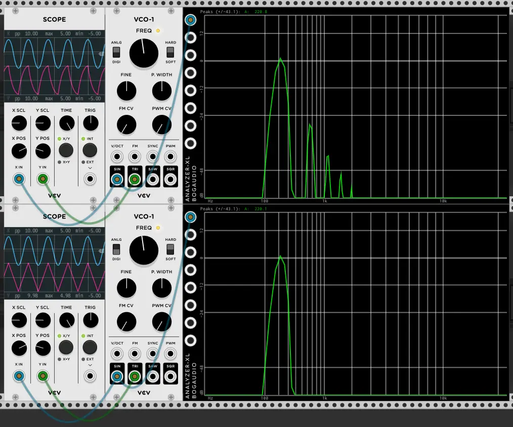
The top VCO is outputting an ‘analog’ emulating signal while the bottom is in digital mode. Look at how the Triangle output shape on the analog mode is smoothed out compared to the digital mode’s sharp edges
You’ll also notice there’s a third wire running into the filter though- into an input labeled ‘freq’. This input modulates the filter’s cut off frequency. You wont visually see the knob change but you will hear the filter’s cut off change based on the signal applied to this input but only if the ‘Freq CV’ knob is turned up. The ‘Freq CV’ knob is what’s known as an attenuverter (a portamento of ‘Attenuator’ and ‘Inverter’). This knob, when facing dead center says ’let nothing though’ while all the way right lets the full signal (from the freq input) though, and all the way left lets the full signal though but inverts it first. Leaning right but not all the way will ‘Attenuate’ or weaken the signal first. I think you get the idea.
So say we put the big ‘FREQ’ knob dead center, and give the ‘FREQ’ input jack wire carrying a very slow sine wave that goes between 0 and 10V, and set the ‘FREQ CV’ knob all the way right: This will bring the cut off higher and higher from it’s starting position, and then bring it back to the starting level. If we instead turn the ‘FREQ CV’ knob all the way left, it’ll bring the cut off frequency lower before turning back around and coming to it’s starting position. Putting it at a slight lean right will still do the same as we started with, but will have less of an impact, making the sound much less ‘jumpy’ and tame. Really, that’s what attenuverter’s are for, taming an input signal.
Here, I’m showing modulating the filter frequency manually as well as showing what resonance is- it boots the signal right at the cut off frequency
Here, the input to the cut off frequency is modulated with an ‘LFO’ or Low Frequency Oscillator, which much like the VCO outputs a simple signal, but in this case the signal is low frequency, usually below human hearing range:
Alright, that’s fine and all, but the cable going input to the ‘FREQ’ control on the VCF is coming from something called an ‘ADSR’
So the adventure continues. ‘ADSR’ stands for ‘Attack, Decay, Sustain, Release’ and it does exactly that. But before we understand the output of an ADSR we have to look at it’s input- ‘Gate’ and ‘Retrig’
‘Gates’, in modular, are simply a positive (sometimes needing to be 5V or higher) signals that represent that something is happening. Usually, that a key is being held. And that’s exactly what’s going on here. When you hold a key the ‘Gate’ output of the MIDI->CV module is active. When you release it, the output goes off. You can see this by looking at the green indicator light where the gate output is on the MIDI->CV module when you hold or release a key. ‘Retrig’ is similar, though it only outputs a short pulse every time you press a key. This is handy because you may press a second key while already holding one key, meaning the gate output should stay on, but the retrig output will have sent a pulse each time you pressed a key (once when you pressed the key your holding, another time when you press a different key while still holding the original key).
So, back to the ‘ADSR’ an ADSR generates a signal that looks like this:
That is, voltage will follow this shape over time. The ‘Attack’ knob sets how long it takes to reach the peak point, the Decay knob set’s how long it will take to reach the sustain level, the sustain knob set’s at what level the sustain should be held at, and the release knob set’s how long the note should take to fade out from the sustain level after the key is released. Take note, the sustain knob controls a level, while the other three control time:
Alright, so when the ADSR get’s a gate signal it’ll go though the Attack and Decay stages and wait at the Sustain level until the Gate is released or a Retrig signal is sent telling the ADSR to repeat the Attack and Decay stages.
So, this output signal is fed to two places, the first is the frequency knob we saw before. This will result in the frequency cutoff going high then coming down to a reasonable level, then cutting down to just low frequencies as a note is released. The other place the signal goes is into the mixer:
The mixer in this demo patch is super simple. It has 4 inputs, with one output. The sliders let you set the level of each input, and the ‘CV’ input of each slider let’s you externally control the slider. Because the ADSR is fed into this input and the ADSR output is at 0V unless you hit a key the mixer actually mutes the signal until a key is pressed and then lets it play, fading out over the release period. The mixer also has one big volume knob ontop to set the master output volume of all 4 channels combined. Essentially the volume follows this shape of the ADSR signal over time. In times like this, the ADSR signal is called the ’envelope’ for the sound. Really, the mixer is just a combination of multiple of a simpler component though, the VCA or Voltage Controlled Amplifier. This name is a bit misleading though, as really VCAs are usually used to bring a sounds volume down, like an attenuator. To show the simplest case I’ll hook up a LFO to control a VCA’s level, in turn changing the level of the signal passing though:
Also, above you’ll see I used a 3rd party oscillator instead of the VCO-1 you’ve seen so far. Pictured is ‘Basal’ from the ‘Vult-Free’ collection of modules available on the VCV library page.
To get modules from the VCV library you’ll need to make an account on that website, add the module collections you want, sign in the VCV rack software, and update your modules. Once the modules are done downloading you’ll be promoted to restart rack and they should be installed. If you’re looking for a few packs to grab to get started, but not be overwhelmed, I recommend Valley, Bogaudio, Impromptu, Vult, Befaco, Alright Devices, Audible Instruments, Erica Synths, Hora, and MindMeld. This will still probably be enough to overwhelm you a bit, but it’s a really good starting place.
When you’re looking to grow a bit: Aria Salvatrice, Blamsoft, Flag, Frozen Wasteland, Lindenberg Research, Geodesics, Instruo, Nysthi, Starling Via, Stoermelder, Wiqid, and ZZC are all very good.
Of course, this list is far from exhaustive, there are a ton of other good modules in VCV, but these are the collections I find myself using the most. If yo’re down to pay for some modules, I really recommend VCV’s Parametra and Host, as well as Vult’s Premum and Compacts collections. Slime Child Audio’s Moog Subharmonicon inspired modules are great too. If you’re a fan of 808 sytle drums, Hora’s analog drums collection is worth a look. If you’re really itching for a better sequener and don’t want to use an external program, check out ZZC’s Phaseque or Geodesics+Vult Hexaquark.
Note, that a few modules are not available in the VCV library, and instead you may need to install them manually. see Installing plugins not available on the VCV Library from the offical VCV manual for more information.
Finally, the output of just the first channel of the mixer is fed into the scope so that when you press a key you can see the signal your generating. To understand this it’s easiest to just drag the cable coming out of the VCO’s ‘SAW’ output to the VCO’s ‘Sine’ Output. Now when you press a key instead of seeing a saw wave you should see a sine wave.
Finally, I want to mention that at least by default this setup is ‘Monophonic’ (Mono = One , Phonic = Voice) meaning that even if you hit 2 keys at once you’ll only hear the note from the last key you pressed. We’ll explore Polyphonic (Many Voice) and Paraphonic (Para = beside, or side by side) systems later.
Let’s make a simple generative track, to start with we’ll need some drums. Here’s what we’ll be setting up:
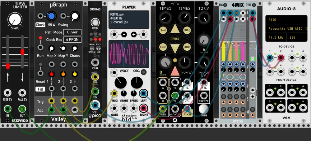
So first, let’s break each module down by function. The uGraph module (2nd on left) is a generative trigger sequencer, it generates drum rhythms for us. It has it’s own built in clock, but an external clock signal can be provided (turn the clock knob left until it says Ext. then provide a clock input that’s multiplied by the rate specified in the clock res box, in this case it wants 4ppqn or peaks per quarter note, so, if you want to a 120 bpm drum line, you’ll want to send a clock signal that’s multiplied by 4. Some modules will sync on 1ppqn or 24ppqn, etc. So, just be aware that you may need to multiply your clock signal some times.) though here we’ll use the internal clock. This module sends out 6 triggers, where the three ‘accent’ (Acc) triggers are a strict subset of the main trigger outputs, that is there will only be an output on Acc when there is an output on Trig, but not always. uGraph will generate the three trigger sequences such that the left most trigger output ‘fires’ the least often and the right most the most often. This works well for setting up a common drum machine with kick, snare, and hat sounds so that the hats are frequent, the snare less so, and the kick a steady beat, but not overpowering. Of course, this isn’t how you have to use it, and you can always add more trigger output patterns in VCV simply by sending two uGraph modules the same clock. Again, for now one module is fine. Finally, it’s notable that this pattern will repeat, but a new pattern can be selected with the Map X and Map Y knobs.
Alright, so uGraph is generating the drum triggers, think of it like the human swinging the drum sticks, but with only uGraph in there’s nothing to hit. so let’s add the basics. Grab a small Nysthi Mixers as pictures 2nd to last above and hook it up to an audio module as well. Then, grab the Erica PicoDrums module and place it in. Now, hook up two of the trigger outputs to the picoDrum’s TR1 and TR2 trigger inputs, take the PicoDrums output to the mixer. After turning down the mixer module’s master out a bit to make sure you don’t play too loud of a sound, hit ‘run’ on the uGraph module. Currently, both of the drum sounds on the PicoDrum are set to the same sample, so you’ll want to move the big ‘ctrl’ knob at the top to select a different sample on drum1, then switch to drum2 with the switch, and pick a good sample for drum two as well. You should now have a good drum pattern started!
The problem with the PicoDrum module is that it has some baked in drum sounds that can’t be changed (well, okay, the real eurorack version they can be, which actually makes it a good value, but I digress) but the sounds are still samples, that is they’re just audio files being triggered to be played back. So, why not use something where we can pick our own sample?
You’ll need some drum samples to get started, so just to get you started here’s a decent sample pack: https://soundpacks.com/free-sound-packs/nyc-drum-kit/
Download, extract, etc. that folder and in VCV place the ‘Player’ module as pictured above. Right click the module, select ‘Load Sample’, and use one of the sounds in the folders. You should now be able to trigger the player module and get sound out of it the same as the PicoDrum module. You can mess with some of the controls to get a feel for what you can do with the player Module. If you’re having fun with that, you may want to look at the ‘Simpliciter’ module from Nysthi for an even more advanced sampler (also check the “samples” section below).
All of this is cool and all, but we’re just playing back and manipulating sound files so far, so, let’s look at the next type of drum: synthesized drum. Synth drums can be made to sound very close to real drums (this is generally called physical modeling, you’ll hear the term a lot more for string synth sounds though) but can give sounds that no real drum would be capable of either. In the patch above I have ‘Meta’ from starling generating a low bass drum sound, but you can generally tweak synth drums into whatever sound you want, albeit some module will be better at different sounds, for example Vult’s ‘Trummor’ modules excel at kick and bass drums. You can also make synth drums from basically anything just by thinking about the sound a drum makes. Generally, a drum is just a sound with a really sharp attack and a pitch that changes at it releases, so, this, while not the best, is a decent drum sound:
anyway, so now the last relevant part of the above patch worth understanding is the slew is just making it so we get a nice envelope generated by the Acc output, that slew is changing the pitch decay time on the synth drum (Meta) so that on accent outputs the low drum lasts a bit longer and has a slightly different sound. Just look at the signal on a scope in VCV if you don’t fully get it.
A bit of an aside #
Some people will try to get you to try various substances to be creative, to make better music, etc.
If you want to get high or drunk, go for it- but don’t let it turn into a creative crutch. You don’t need it.