31 - Control Systems #
What are control systems? Well, the easiest way to answer that is to list the things control systems typically do:
What Can Control Systems do? #
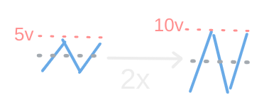
Amplify an input: #

Reduce the complexity of user input or change its location #

ex: Floor button on an elevator- you don’t need to input a height off the ground for what floor you want to be on, nor do you need to enter values to compensate for how quickly it should get to its max speed or how fast it should slow down.
ex: Literally any remote controlled device, like drones
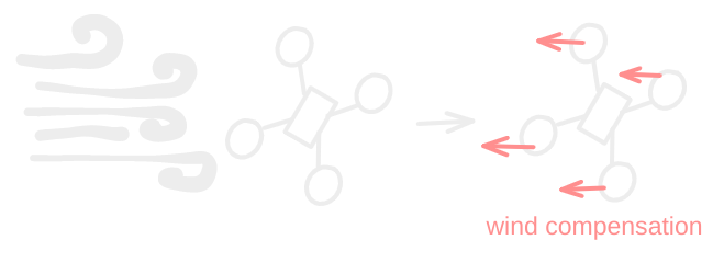
Compensate for undesired input #

What are the primary concerns when making a control system? #
-
Transient Response - when we change states, we want the system to respond, but not so fast it breaks or so slow we’re stuck waiting
ex: Dose the elevator take too long to get going or does it accelerate too quickly and make your stomach turn over
I like to think of this as “When I kick it, what happens”
-
Steady-State Response - when the system reaches a steady-sate, is it behaving how we want
ex: Did the elevator stop right at the right spot, or did it under or over shoot? Is it still moving up and down a bit (oscillating) even after it reached the destination floor?
Put simply, is the output what we want, or did we overshoot, undershoot, or did it just never stop changing.
-
Stability - Is the output bounded, is there any input which might cause the system to self oscillate or otherwise lose control
ex: A microphone next to a speaker will cause that awful feedback whine as soon as any input is applied (even background noise) this is instability
Put very simply: is there a situation where the system goes to shit
-
The same concerns as everything else - Keep cost down, reliability up, and complexity reasonable for the problem.
Block Diagrams #
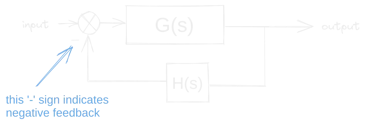
When we represent these systems, we’ll typically use block diagrams that look something like this:

Though usually we’ll have to put in some work to make them this simple - often there are multiple blocks between the input and output, sometimes with non-trivial relations to one another - and we’ll need to simplify it down to this form.
You’ll probably notice that the block that’s actually working on stuff here has an argument of s not t as you’d expect for signals relating to time. This is because in control systems, we’re usually going to work with things after having gone through the Laplace Transform. I won’t spend really any time going over that in this chapter, if you need a refresher, see Chapter 27: Signals & Systems. For the most part you’ll be able to get by just using tables and some clever thinking to find the transformations between the time and s-domain equations. I don’t want to get bogged down in the math before we see a use for it, though, so let’s move on to some terminology that will make this block diagram business make some more sense:

- Input:
- Input Transducer:
- Summing Junction:
- Controller:
- Disturbance:
- Plant:
- Output:
- Sensor:
Another thing to note, is that this system, as depicted, is Closed Loop System because, well, there’s a closed loop where the output is fed back though a sensor into the input. In an Open Loop System there would only be one straight line of boxes, no loops, though there will likely still be disturbances, even if they’re not actually drawn. Via some math we’ll look at in a bit, you’ll see we can convert any closed loop system into an open loop system, which will generally be necessary for analysis and design.
We’ll generally look at two kinds of systems- those with and those without feedback, so let’s start with that and why it matters:
Feedback #
As an example of negative feedback, the diagram might represent a cruise control system in a car, for example, that matches a target speed such as the speed limit. The controlled system is the car; its input includes the combined torque from the engine and from the changing slope of the road (the disturbance). The car’s speed (status) is measured by a speedometer. The error signal is the departure of the speed as measured by the speedometer from the target speed (set point). This measured error is interpreted by the controller to adjust the accelerator, commanding the fuel flow to the engine (the effector). The resulting change in engine torque, the feedback, combines with the torque exerted by the changing road grade to reduce the error in speed, minimizing the road disturbance.
Do note here, the reference to negative feedback. This is an important point, in many systems, we want the signal that’s fed back in to not tame the system, not make it push harder. Of course, there are times that’s helpful too, so positive feedback does have its place.

What about Feedforward? #
[TODO]
https://vaclavkosar.com/ml/PID-controller-control-loop-mechanism
https://www.wescottdesign.com/articles/pid/pidWithoutAPhd.pdf