The Tools of the Trade #
Okay so we know we have voltage, current, and power. Additionally, you’ve probably heard about terms like resistance, impedance, capacitance, and maybe inductance before. What the heck do these mean? Well, to each into a more tangible context, lets look at the tools used to measure each.
Building, fixing, and analyzing circuitry requires the use of a some tools and appliances, so let’s look at the basics of working with electricity by looking at what purpose the tools serve. While there are many more than those listed here, these are the most important ones and should be all you need for most applications.
Unfortunately, there will be some cost involved in getting these. I’ll do my best to give you advice to keep the cost down while still getting good equipment as we go over what each is for. I do really recommend having at least the most basic version of these tools to get started.

Character owned by Vega, art by Shade
If you go for the absolute cheapest options and hunt for used equipment, it’s reasonable to get everything for about $175. I realize to many that’s a tough pill to swallow, so if you just can’t do that, that’s 100% okay! You can get by for a good while with just a multimeter, the power supplied by a microcontroller, and simulation software. That brings the actual upfront cost down to around $30.
Of course, that’s not counting the actual parts needed for whatever you’re building, though parts tend to actually be quite inexpensive.
The Multimeter #
The Multimeter generally serves three roles: A voltmeter, an Ammeter, and an Ohmmeter. These are for measuring Voltage (in Volts - V), Current (in Amps - A), and Resistance (in Ohms - Ω (omega)) respectively. Furthermore, most multimeters can do continuity testing (checking if two points are connected).
Resistance and the OHM meter #
Resistors do one thing- resist current.
Using the ohm meter function of your multimeter you can find out the amount of this resistance measured in ohms (ohms are represented with a capital omega, Ω) using an ohm meter is simple, just poke and prod with at least one component in between the leads. If there’s nothing in between - that is the leads are touching one another- there will be no resistance, if there’s no way for a DC voltage to get from one point to the other, that will be infinite or ‘overload’ resistance
But, uh, why should you care.
Well, resistors on their own are mostly useless - well, except for making heat. In most circuits though waste heat is something we want to avoid.
The reason you should care is because we can use resistance for doing important things in a circuit. For example,

in this circuit we have two resistors of the same value in parallel hooked up to a voltage source. Because they’re the same value each will have half the voltage of the source across it. It’s a voltage divider!
While this divides it in half each way, we could adjust the values to get different ratios.
This isn’t the most efficient or by-any-means the best way to get a lower voltage, but it does work, and in some applications is a perfectly reasonable solution.
Voltage, Ground, and the Volt Meter #
Voltage can be thought of as the ‘pressure’ in a hose. (And a battery the pump)
However, this pressure is relative to another point, the point we usually take reference to is called ‘ground’, though this doesn’t have to be the case- you can measure the voltage across a single resistor or other component too.
Just remember, measuring the voltage with both probes at a point or along the same wire doesn’t make sense because a volt meter only tells you the voltage difference between two points. This would be like seeing the pressure difference in hose between two nearby points, obviously the pressure of one point minus the other will be 0.
In general, there are two primary ways you will work with voltage- AC or DC, these stand for Alternating Current and Direct Current.
DC is simply a constant voltage level output. AC on the other hand is any time varying signal, usually (but not always!) periodic (repeating) and most commonly a sine, though many other waves are used like square, triangle, saw, and any mixture of these, including the same signal with a DC offset. Not here that AC is technically referring to the current having this shape and not the voltage, it’s just that in the basic scenario with a constant load, the current and voltage waves will look the same

Your multimeter will likely have two different settings for measuring voltage, one for DC and one for AC.
Of note, most inexpensive multimeters are not true RMS (Root Mean Square) meters, meaning the reading of AC voltage is not an accurate measure of how much energy the wave can deliver unless it’s a clean, no DC offset sine wave. Imagine a square wave like the above, with the same height, but where the peaks are thinner, with longer periods of rest in between (this is known as having a lower duty cycle), in this case the wave would still have the same Voltage Peak-to-Peak (Vpp) value but on average wouldn’t be able to carry as much energy.

Of note, from a mathematical perspective all time varying signals can be represented as an infinite number of sine waves added together, this is actually used to do practical computation in many things, and what is used if you ever want to get into digital signal processing. I only mention it here because I foresee it being a rabbit hole someone could fall down when trying to gronk what RMS is. Again, we’ll talk more about all of this latter, so I’m going to move on for now.

If you’re feeling really adventurous Chapter 28 - Signals & Systems has more resources on this topic, but we’ll get there eventually.,
Current and the Ammeter #
If voltage is the pressure in the hose, then current is how much water actually flows. This analogy holds up too, because if we use a resistor to kink the hose and the flow is restricted, the current will go down.
If you were to stick a fork directly into the wall outlet (Don’t), all the current the wall can give will try to flow though. It’s like hooking up a fire hose to your spigot- at least until the breaker blows (the breaker is there to prevent exactly this).
Now, when you plug in any normal appliance you (hopefully) don’t blow a breaker. Plus, you know some things use more power than others. So, obviously each device restricts current draw to some extent.
Just placing a resistor in line will do this. In fact, you’ll often hear the term “current limiting resistor” for exactly this reason. As mentioned before though pretty much all resistors do is produce heat, so unless you’re after a space heater usually that power will be used doing something more useful (making light, moving a motor, etc.)
Still, in most cases, we can roughly model those useful effects the same as we would a resistor and make our lives easier.
This brings us, finally, to the most important equation in all of circuitry, behold:
OHM’s Law #
\(V=I\times R \implies R = \frac{V}{I} \implies I = \frac{V}{R}\)It’s really just one equation, \(V=I\times R\) , but the different ways to rearrange it are important.
As for what it actually means: that is, Voltage = Current * Resistance
or, Resistance = Voltage / Current or, Current = Voltage / Resistance
I can not in words convey how important this equation is. If there is any single equation you should have related to electricity committed to memory, it is this one - though, before you commit it independently, you should consider how it relates to the power equation from the start, and how you can substitute in ohm’s law.
\(P=I\times V \implies P = I \times I \times R \implies P = I^2 \times R\)The good thing here is that if you know any two of the four (P, V, I, R) you can find the other two, you just might have to do a smidgen of algebra.
Back to the ammeter,
To measure the current though a circuit we can’t just probe between two points as before though. Instead, the probes need to form the exclusive path that part of the circuit can flow through.
In practice, this means the wire you want to measure current through will need to be cut and the ammeter’s probes hooked up at either end, making the meter part of the circuit. If you want to measure flow, you actually have to put the flow meter in line!
Current, just like voltage, can vary, and in AC circuits usually does. This leads to some more interesting topics like “power factor”, but we’ll get to that later.
Continuity Tester #
The continuity tester does exactly what it’s name implies, it makes sure two points are connected electrically.
If you have a piece of metal and put both probes on, it should beep, but if you put the probes on rubber, they clearly will not be. The continuity tester isn’t really much different from the ohm meter in operation, and many will actually display the resistance if there is any.
The main use is that it beeps when the resistance is low enough to be confident two points are electrically connected or for checking that two points aren’t connected (such as ensuring there’s no short between two pins of a small part)
Of note, the continuity tester is not magic. It works by applying a small voltage to the circuit and checking if it can pick up that voltage on the other probe. If you’re working on something particularly sensitive, this small voltage could destroy it. This is why it’s good to know how your tools work!
The Lab Power Supply #
Lab Power Supply Units or ‘PSU’s are useful because, unlike your phone charger which puts out a singular voltage of 5 volts (ignoring fast charging), they can have their output voltage varied. Usually the range is between 1 and 35-ish volts, though if you need more, there are options.
Though, probably most important for a lab power supply is current limiting, useful when you’re unsure of how much current your circuit might sink or need it for safety. Sometimes you may just want to hook up your freshly made circuit with the current limit very low as a method of finding if there’s a short without making the entire thing go up in smoke.
This is a good time to bring up the common myth “It’s not the voltage that kills you, it’s the current!”
Bullshit.
Consider the following required viewing before you ever go near a live circuit, but don’t let his confidence lead you to believe electricity isn’t dangerous. It is, and that’s his real point. It can and does kill electricians and electrical engineers regularly. More often than not due to impatience.
I do high voltage wood burning. This is an activity that kills about 30 people a year. How do I do it safely? I never get close to it while it is on - I throw the switch from a distance. Cool as it looks, it’s not worth risking getting bit by the arc and having it stop my heart.
When looking for your first lab PSU, it may be overwhelming. You’ll see some going for $40, and some going for $500. Generally, the cost difference gets you a few things: Multiple channels and cleaner output (undesired AC ripple in DC supply = bad). For starting out, nobody wants to spend that.
The biggest difference the high end ones will often have is being multi-channel and how clean the output is.
Being multichannel is basically just two (or more) lab power supplies glued together. This can be handy for powering things that expect a “split rail” commonly OpAmps (a part we’ll talk about later) will want to be powered with both +12 and -12 volts. You need two supplies to get both (and you have to wire them in a special way to do it)
Fortunately, you can get around needing two supplies to start with by using a little module to generate those voltages for you from another supply. These are usually ~$5.
Output cleanliness is a matter of how constant is the signal coming out. If you set it to 10V but it’s a jittery signal randomly swinging from 9V to 11V super rapidly, that’d be super dirty. You want it to be constant and smooth. This example is extreme though and it’s unlikely you’ll be working on anything where you need that clarity for a while.
So, while there are some downsides, I recommend grabbing pretty much the cheapest lab power supply you can find that allows for setting current limiting (constant current, or CC is the same thing) and one of these boost/buck converters. Just be aware of its limitations and confirm its voltage with your multimeter. Also, confirm it’s current limiting works by intentionally drawing a higher load through a resistor and checking that the voltage drops in response.
For example, if you set the supply to 10V and hook up a 100Ω resistor, you should expect that to draw \(I = \frac{V}{R}\) → \(I = 10V/100Ω\) →.1A (usually this would be written as 100mA)
So, if you set your supply to max out at 50mA, you should see the current remain constant at 5mA but the voltage drop to ~5V. If this doesn’t happen, current limiting may not be working.
if you can find a used dual or tripple-output power supply where each channel has adjustable voltage and current limits at a good price, go for it. I nabbed a dual output supply on EBay for around $50 + another $50 shipping since it’s a good 30lbs or so, but that’s still a chunk of change.
The Frequency or Waveform Generator #
Frequency generators can be used to output a signal that is alternating, unlike the DC signal of the Lab PSU. Usually they’ll support a range of wave shapes, frequencies, amplitudes, and DC offsets. Many support far more than this, though the applications for the more advanced modes are few. If you’re just starting out, you can (with precautions) just use the audio output of your computer or buy an inexpensive one for under $20, unlike the expensive example below:
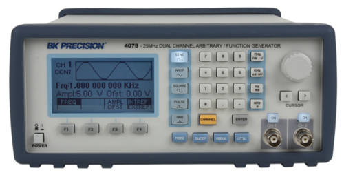
https://en.wikipedia.org/wiki/Arbitrary_waveform_generator
Of all the equipment on this page, this is probably the one you can most easily scrape by without or DIY cheaply enough with a microcontroller and a Digital to Analog Converter (DAC) - something I’ll cover how to do later.
If you’re only working on digital electronics, it’s less likely you’ll need one, but if you’re in the analog world, they’ve very helpful for checking the frequency response of your circuits. For example, say you want to make an simple circuit to boos the bass of an audio output - You’d want to check what frequencies it raises and what frequencies it lowers.
This example is actually sorta bad because the better way to do that is to run white noise though the circuit and look at the frequency response as a whole. But, trust me, there are plenty of times you’ll just want a basic signal - like a sine wave at a specific voltage and frequency - to test with.
The Oscilloscope #
The oscilloscope (or OScope or simply Scope) allows you to see an AC signal and how it varies over time as a plot of Voltage on the Y axis and time on the X.
More simply, it lets you watch how your circuit behaves over time.
Most OScopes will allow you to look at multiple signals at once, with one overlaid on the other. Furthermore, most support X-Y mode, where the plot is actually the voltage of one input as the X axis and the voltage of another as the Y, moving a dot and it’s trail around the screen. In fact, this is how the first computer monitors worked:
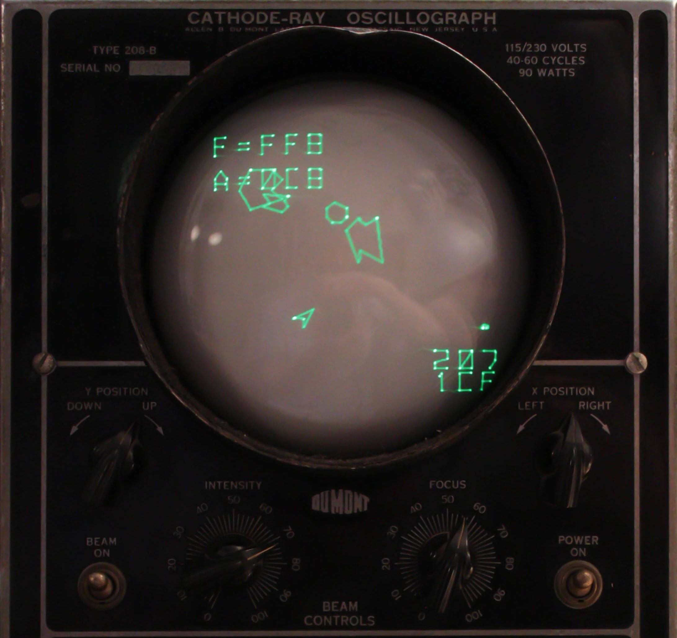
Modern OScopes look much different than their phosphorescent green ancestors, though:
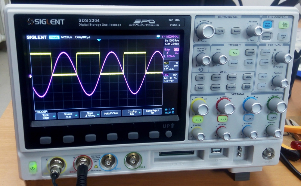
However, a decent ‘Digital Storage Oscilloscope’ or DSO like the one above run a minimum of $300 at the time of writing, so many hobbyists opt for older scopes like this one:
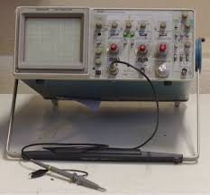
Note, a lot of hobbyists will try to get by on a really cheap new scope (less than $100).
There’s a particularly popular really cheap (often under $10) exposed red PCB one and just… don’t. Either get a used scope (often around $100) or get something good outright, as for “good” I’d really recommend the Rigol DS1054Z
If you absolutely want the cheapest possible option, you can go through the mild headache of setting up a Raspberry Pi Pico (~$4) with Sigrok-Pico. You’ll need some resistors (very cheap) and probably the breadboard with the pico’s pinout. Total price should be around ~$15. These are going to be god awful analog inputs though - they’re only 7-bit, so you get 128 different values out and the max sample rate is 120Msps… not awesome, but maybe you don’t need much.
Regardless, this still hasn’t really told you why you’d want one.
While the multimeter is great as a quick diagnostic tool, it only tells you the value of whatever you’re looking at in that moment. Usually, for a circuit to be interesting, different signals are changing in values all the time. If it’s digital, those values should just be on or off, if it’s analog, they could be anything.
But that brings up the first use - confirming a digital signal is actually okay.
It’s pretty common for a signal you expect to transition between on and off (or off and on) more-or-less instantaneously to have some switching time. Making the what-should-be-a-square wave look like more of a hill. This can cause the digital circuit to freak out because the value while in that slope isn’t really on (1) or off (0). If you’re curious about this, look at the Wikipedia page for eye patterns.
If it’s analog, well, the scope is your way to look at what is going on at all. You can use it to figure out what frequency a signal is, what it looks like, what voltages its swinging between. You can hook up two signals and let the scope to math on them to see how they’re related in some way (if you subtract them, do they cancel out?)
It’s also usually possible to setup the scope to only capture a brief window when a signal changes. Say you know that right after one signal turns on you expect another signal to do a lot of things, but very briefly. You can set this up to trigger on that signal and record that otherwise hard to isolate signal.
For most modern scopes, this is only scratching the surface. For example, they’ll usually let you view the spectrum of an incoming signal as well - but we’ll get there with time.
Quake on an oscilloscope (YouTube)
The Logic Analyzer #
Logic Analyzers… analyze logic. Who could’ve guessed?
But what does that mean? Well, in reality they are somewhat similar to an oscilloscope in that they show a voltage over time, the difference is they only show either on or off over time based on the set TTL (Transistor–transistor logic) voltage. This lets you eavesdrop on the digital communication going on over a wire. Here’s an example output:
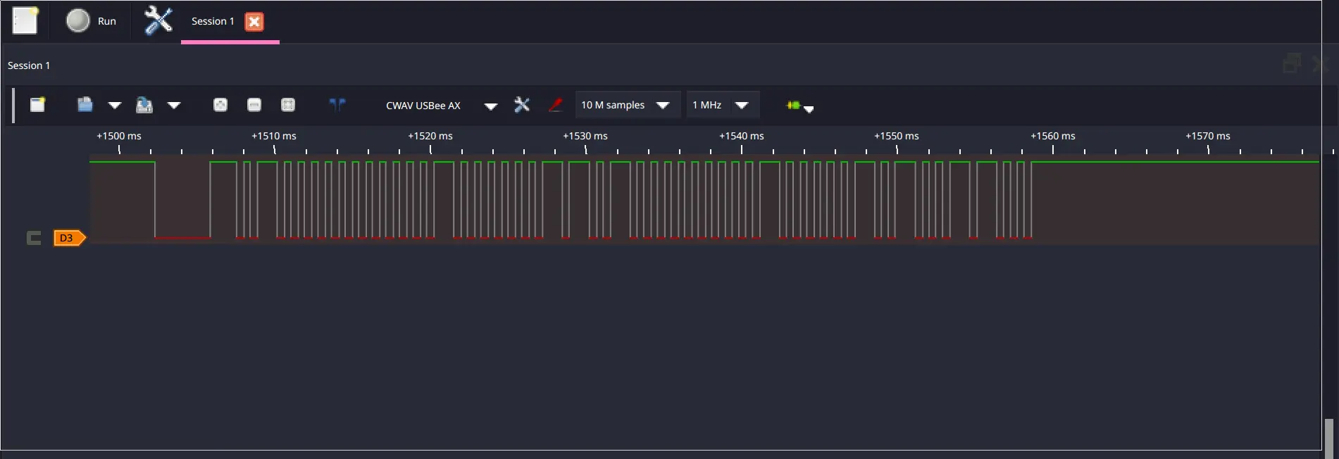
In this particular encoding, the longer high bumps represent a 1 and the short high bumps a 0, so you’re looking at the binary that was sent over a wire. While it’s common that a wire sends raw high for a 1 and low for 0, other schemes, like the one above, are used a lot too. For most encodings the software can actually be used to decode the received data into raw binary or if it was human-readable characters it can get those characters out for you too.
Using a logic analyzer is pretty simple, most today are connected to your computer over USB and then use software like Pulseview as shown above, then you just select the sample rate (how many times per second to check the wire, here 1MHz) and the number of samples to collect and hit start. You may want to set up a trigger too - which does more-or-less the same thing as for the OScope above.
Most logic analyzers support 8 or more simultaneous data streams, though in the picture above I’m only using one.
You might be wondering why you’d even want a logic analyzer. Isn’t this just an OScope but worse?
I mean, sorta, but:
- All logical analyzers will provide data decoding based on protocol
- Some scopes will do this too, but it’s less common
- Logic analyzers will usually have a lot more inputs (Between 8 and 32 is common)
- Usually for a given sampling rate they’ll be cheaper
- Actually, they’re just cheaper in general
- The window of time you can record is generally much, much longer
- Often, this time window is effectively infinite - as long as it can stream data to the computer as fast as it can capture it.
Probably the most common use of a logic analyzer is to check that code running on a small processor is causing the correct signals to be output on some pins and at the correct time. As you should’ve seen from the previous chapters, sometimes writing that code can be error prone, so having a way to verify it’s working correctly - or look at the signal when you know it’s not - is quite handy.
[TODO] Evaluate Using a pi Pico as a logic analyzer
Soldering Iron #
It’s a big ol’ heat stick. Grab some solder and melt it around a component to bond two things together with a nice conductive glob of metal.
https://www.digikey.com/en/maker/blogs/rohs-vs-non-rohs-soldering